The capability of many UTP-based Ethernet standards to use a cable length up to 100 meters means that the majority of Ethernet cabling in an enterprise uses UTP cables. The distance from an Ethernet switch to every endpoint on the floor of a building will likely be less than 100m. In some cases, however, an engineer might prefer to use fiber cabling for some links in an Ethernet LAN, first to reach greater distances, but for other reasons as well. This next section examines a few of the tradeoffs after discussing the basics of how to transmit data over fiber cabling.
Fiber-optic cabling uses glass as the medium through which light passes, varying that light over time to encode 0s and 1s. It might seem strange at first to use glass given that most of us think of glass in windows. Window glass is hard, unbending, and if you hit or bend it enough, the glass will probably shatter—all bad characteristics for a cabling material.
Instead, fiber-optic cables use fiberglass, which allows a manufacturer to spin a long thin string (fiber) of flexible glass. A fiber-optic cable holds the fiber in the middle of the cable, allowing the light to pass through the glass—which is a very important attribute for the purposes of sending data.
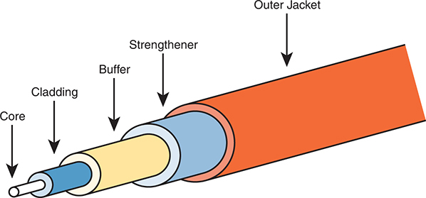
Although sending data through a glass fiber works well, the glass fiber by itself needs some help. The glass could break, so the glass fiber needs some protection and strengthening. Figure 2-14 shows a cutout with the components of a fiber cable for perspective.

Figure 2-14 Components of a Fiber-Optic Cable
The three outer layers of the cable protect the interior of the cable and make the cables easier to install and manage, while the inner cladding and core work together to create the environment to allow transmission of light over the cable. A light source, called the optical transmitter, shines a light into the core. Light can pass through the core; however, light reflects off the cladding back into the core. Figure 2-15 shows an example with a light-emitting diode (LED) transmitter. You can see how the cladding reflects the light back into the core as it travels through the core.

Figure 2-15 Transmission on Multimode Fiber with Internal Reflection
The figure shows the normal operation of a multimode fiber, characterized by the fact that the cable allows for multiple angles (modes) of light waves entering the core.
In contrast, single-mode fiber uses a smaller-diameter core, around one-fifth the diameter of common multimode cables (see Figure 2-16). To transmit light into a much smaller core, a laser-based transmitter sends light at a single angle (hence the name single-mode).

Figure 2-16 Transmission on Single-Mode Fiber with Laser Transmitter
Both multimode and single-mode cabling have important roles in Ethernet and meet different needs. Multimode improves the maximum distances over UTP, and it uses less expensive transmitters as compared with single-mode. Standards do vary; for instance, the standards for 10 Gigabit Ethernet over Fiber allow for distances up to 400m, which would often allow for connection of devices in different buildings in the same office park. Single-mode allows distances into the tens of kilometers, but with slightly more expensive SFP/SFP+ hardware.
To transmit between two devices, you need two cables, one for each direction, as shown in Figure 2-17. The concept works much like having two electrical circuits with the original UTP Ethernet standards. Note that the transmit port on one device connects to a cable that connects to a receive port on the other device, and vice versa with the other cable.

Figure 2-17 Two Fiber Cables with Tx Connected to Rx on Each Cable