Note
If available, find a nearby Ethernet UTP cable and examine the connectors closely. Look for the pin positions and the colors of the wires in the connector.
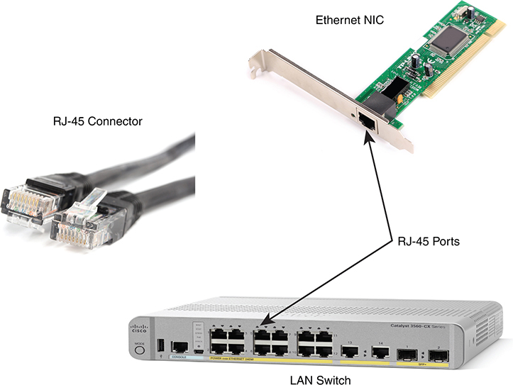
To complete the physical link, the nodes each need an RJ-45 Ethernet port that matches the RJ-45 connectors on the cable so that the connectors on the ends of the cable can connect to each node. PCs often include this RJ-45 Ethernet port as part of a network interface card (NIC), which can be an expansion card on the PC or can be built into the system itself. Switches typically have many RJ-45 ports because switches give user devices a place to connect to the Ethernet LAN. Figure 2-7 shows photos of the cables, connectors, and ports.

Figure 2-7 RJ-45 Connectors and Ports
The figure shows a connector on the left and ports on the right. The left shows the eight pin positions in the end of the RJ-45 connector. The upper right shows an Ethernet NIC that is not yet installed in a computer. The lower-right part of the figure shows the side of a Cisco switch, with multiple RJ-45 ports, allowing multiple devices to easily connect to the Ethernet network.
Finally, while RJ-45 connectors with UTP cabling can be common, Cisco LAN switches often support other types of connectors as well. When you buy one of the many models of Cisco switches, you need to think about the mix and numbers of each type of physical ports you want on the switch.
To give its customers flexibility as to the type of Ethernet links, even after the customer has bought the switch, Cisco switches include some physical ports whose port hardware (the transceiver) can be changed later, after you purchase the switch.
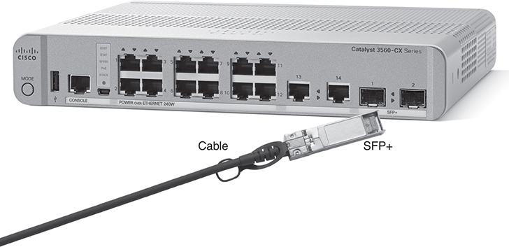
For example, Figure 2-8 shows a photo of a Cisco switch with one of the swappable transceivers. In this case, the figure shows an enhanced small form-factor pluggable plus (SFP+) transceiver, which runs at 10 Gbps, just outside two SFP+ slots on a Cisco 3560CX switch. The SFP+ itself is the silver-colored part below the switch, with a black cable connected to it.

Figure 2-8 10-Gbps SFP+ with Cable Sitting Just Outside a Catalyst 3560CX Switch
Gigabit Ethernet Interface Converter (GBIC): The original form factor for a removable transceiver for Gigabit interfaces; larger than SFPs.
Small Form-Factor Pluggable (SFP): The replacement for GBICs, used on Gigabit interfaces, with a smaller size, taking less space on the side of the networking card or switch.
Small Form-Factor Pluggable Plus (SFP+): Same size as the SFP, but used on 10-Gbps interfaces. (The Plus refers to the increase in speed compared to SFPs.)
So far in this section, you have learned about the equivalent of how to drive a truck on a 1000-acre ranch: You could drive the truck all over the ranch, any place you wanted to go, and the police would not mind. However, as soon as you get on the public roads, the police want you to behave and follow the rules. Similarly, so far this chapter has discussed the general principles of how to send data, but it has not yet detailed some important rules for Ethernet cabling: the rules of the road so that all the devices send data using the right wires inside the cable.
This next topic discusses some of those rules, specifically for the 10-Mbps 10BASE-T and the 100-Mbps 100BASE-T. Both use UTP cabling in similar ways (including the use of only two wire pairs). A short comparison of the wiring for 1000BASE-T (Gigabit Ethernet), which uses four pairs, follows.